Installing wiring, rear view reversing camera, solar panels, domestic battery, fuse box, inverter, switches, LED strips, USB ports and charge controller.
Also check out our video about installing our electrical system.
Throughout the conversion we worked, step by step, on the electrical system. Each phase in the conversion proces usually had some electrical component in it.
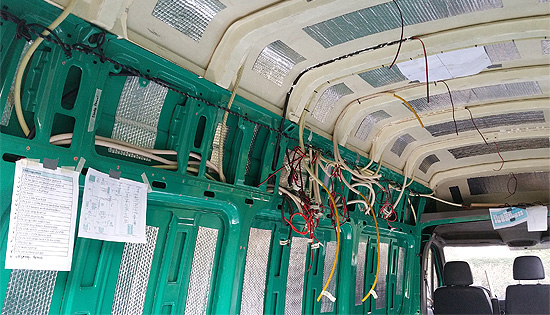
First thing is getting all the wires in. A large part of our design was the electrical system. So when we started the conversion we knew where all the wires needed to go.
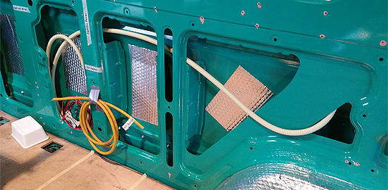
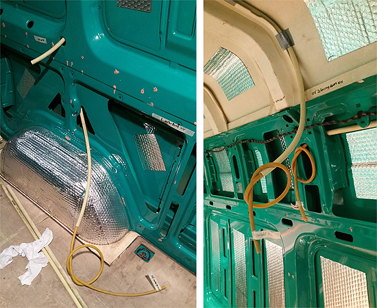
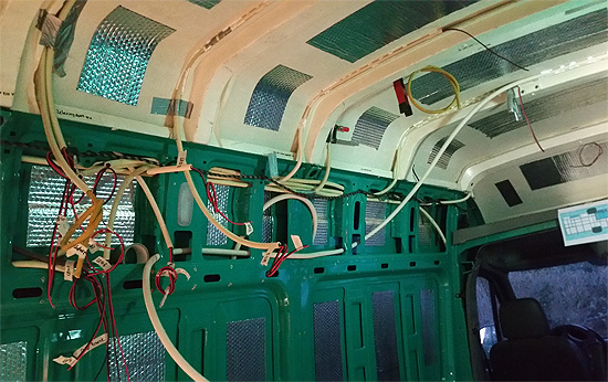
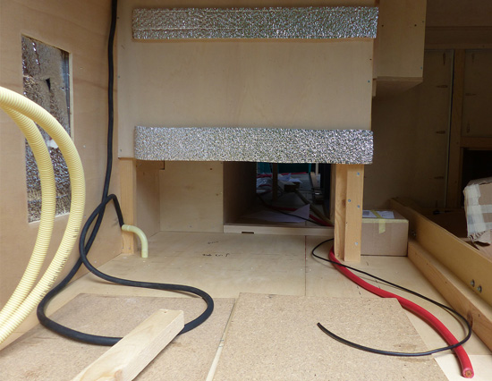
Everywhere we could we put the wires in flexible electrical tubing through the ribs on the side walls, so the wire would be protected. And when in doubt, we pulled through 2 twin cables, just to be sure.
For our low power appliances, like USB chargers en LED lights we used 1,5 mm2 twin autocable (red & black). For the fan, waterpump and diesel heater we used 2,5 mm2 industrial grade twin cable.
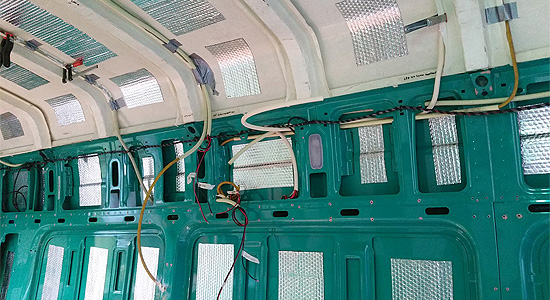
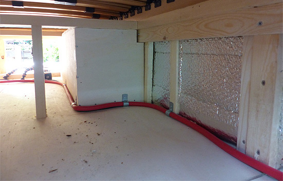
The Mercedes-Benz Sprinter L4H3 super high top has a glassfiber top. On the ribs are niches that turned out precisely to fit the flexible tubing. So we glued the tubes in place. Plus we secured the tubes with zip ties.
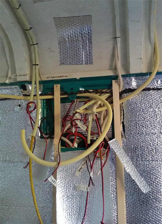
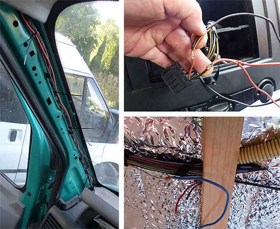
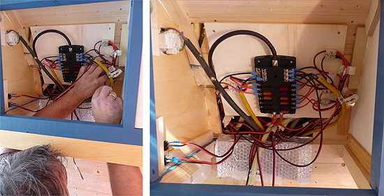
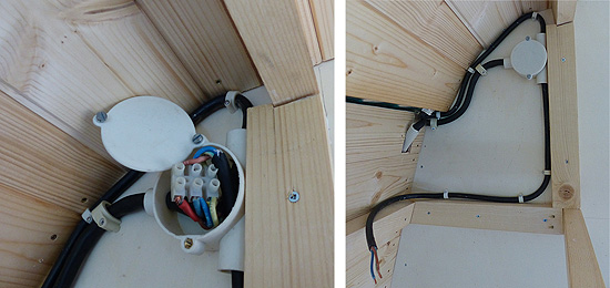
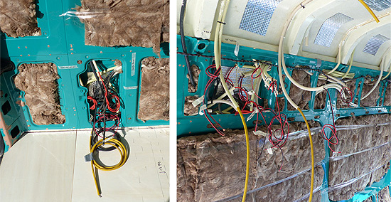
The wiring comes together in two main locations in the campervan. First in the middle of our living space we planned the central fusebox of all the appliances in the van (picture below right). Second in the garage we planned the electrical panel from which all the 230V cables and 12V wires to and from the fusebox originate (picture below left). Also the battery will be located in the garage.
After all the wiring was put in, it would take a few months before we could continue installing the electrical system. First we had to build the interior of the van, before the systems and appliances could be put in place.
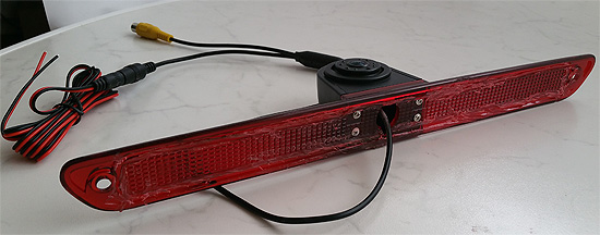
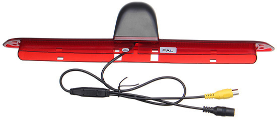
The first appliances we put in place were the reading light above the double bed and the rear view reversing camera. Especially the reversing camera turned out to be an elaborate project. Inspired by Greg Virgoe's video about his reversing camera we bought a similar one.
As our camper doesn't have a rear break light and thus no factory made hole in the roof, we trimmed of the edges on the back and planned to paint the red reflector black and install it on the back of the van. Just like in Greg's video. I did a test with a 12V bench powersupply and everything worked fine.
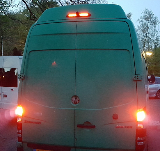
Luckily I procrastinated on this project and I had not painted the reflector black yet. As it turned out our Sprinter van was registered as a company van and after conversion would be re-registered as a 'Motor Caravan' according to EU law. This meant a rear break light became mandatory for our van. So we had to change our plans with the rear view camera. We had to make into a rear high break light after all.
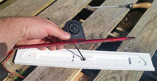
We had to face two facts. (1) we have no factory made hole in the back of the roof of the van and (2) we had allready trimmed the edges of the camera reflector. So we decided to get creative and manufacture our own breaklight.
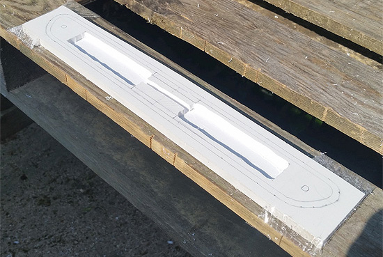
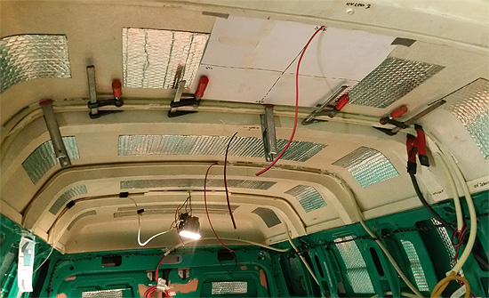
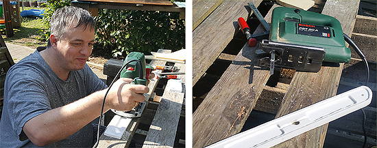
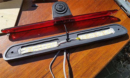
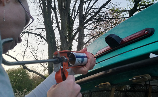
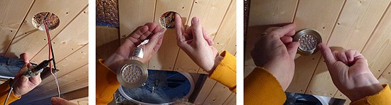
As a base we used a cutt-off piece af 10mm hardfoam board we had laying around. We used a router to cut out the deeper gaps where we would install high powered waterproof LED strips (that we had allready bought for other purposes in the van). With the router we cut the circumference of the reflector, so it would be recessed in the base. Then we cut the foam board to size with a jigsaw. This we spraypainted black.
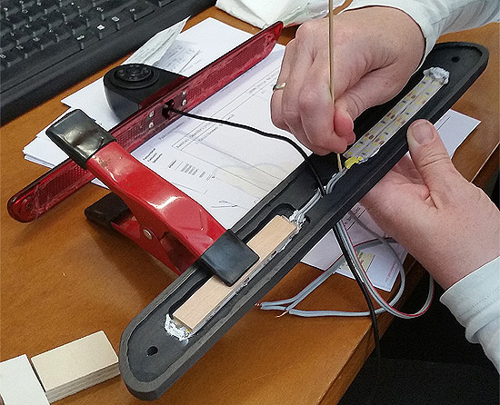
We wired and tested the LEDs and then glued them in place with water resistent sealant. We let it harden overnight. Then we glued the camera with the red reflector in place using black Sikaflex.
How we want to operate the rear view camera is that it automatically starts up when we put the gear in reverse, but also we want to switch it on manually when we want to. For this we first had to find the wire that activates the reversing lights. We used this as the "switched live" wire to connect to the camera.
Also we had to find the wire that activated the rear breaklights to power the lights on the rear high breaklight. Luckily I had a good friend help me with this, as he knows much more about vans then we do.
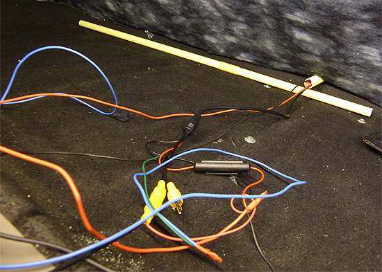
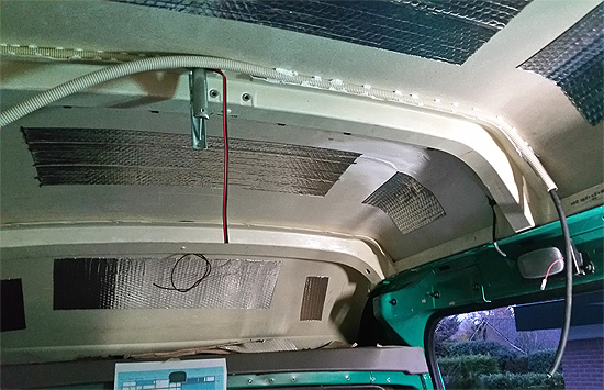
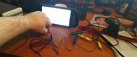
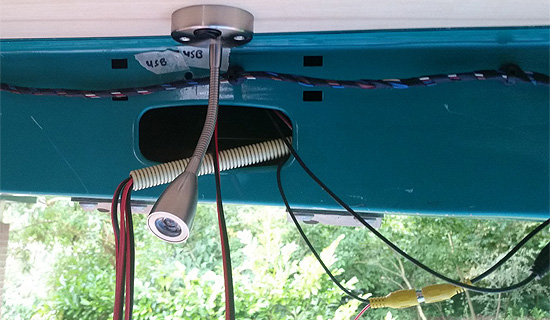
We powered the reversing camera from a powersource in the dashboard and linked these wires back to the bulkhead / storage space above the cabin. Our reversing camera is meant to be clipped to the rear view mirror. Although the mirror is missing in our van (for now) we want the wiring to come down from the bulkhead to the location of the mirror. So we also brought the "switched live" wire (the blue wire in the photos) to this location. Here we connected all the wires and tested the camera. And it worked on the first try.
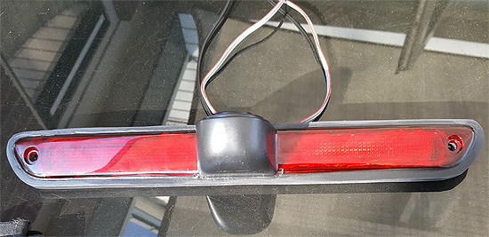
Then it was time to finish up this project and drilled two holes in our van roof in the back. We cleaned the roof thouroughly and applied black Sikaflex. Then we glued the camera on and used bolts and nuts to secure it to the roof. Then we sealed the edges, again with the black Sikaflex. This should never come off again.
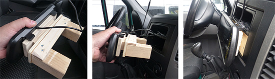
As we were at this stage getting ready for our first trip and still had no rear view mirror, we made an unusual, but practical wooden setup to secure the screen of the rear view camera in the dashboard. It isn't pretty, but it works for now!
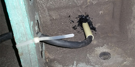
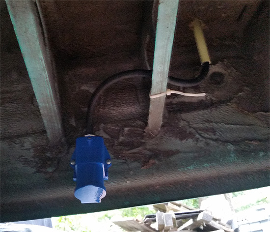
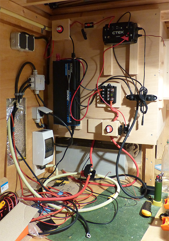
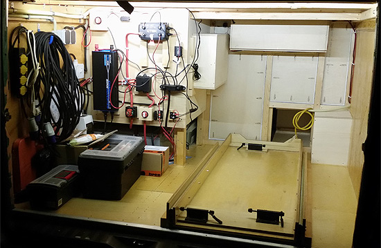
To get shore power one of the first things we did in the garage was getting the 230V hookup point installed. We drilled a hole through the floor of the van, pulled an electrical pipe through and put a 3x 2,5 mm 2 cable in. We sealed the hole with black Sikaflex. We mounted the hookup with selftapping screws. The shorepower is the black cable coming out of the PVC elbow pipe on the left in the photo below.
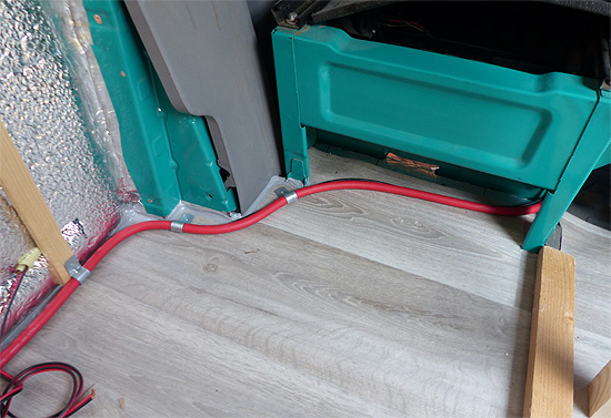
On the right in the photo above you see the 50 mm2 red cable and the 6 mm 2 black cable. These are for connecting the starter battery to the domestic battery via a CTEK D250SA Battery charger that also acts as a battery combiner / relais. As the starter battery is in the front, these cables run through the length of our van into our garage in the back.
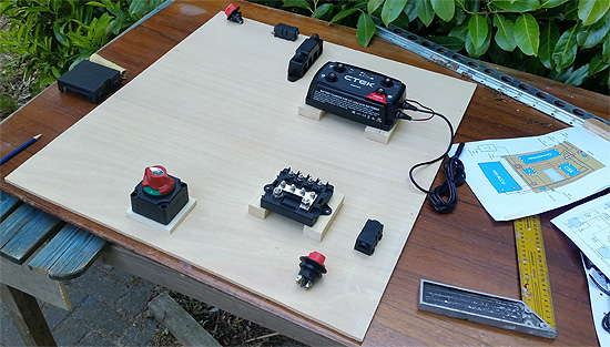
As you can see in our other projects, the bed is now built and it's time to assemble the electrical panel. The panel design was "translated" to a physical panel, with a few minor changes. All the components we places on a small wooden base, so cables can run underneath them, if needed. Also this keeps all cables visible in case of troubleshooting.
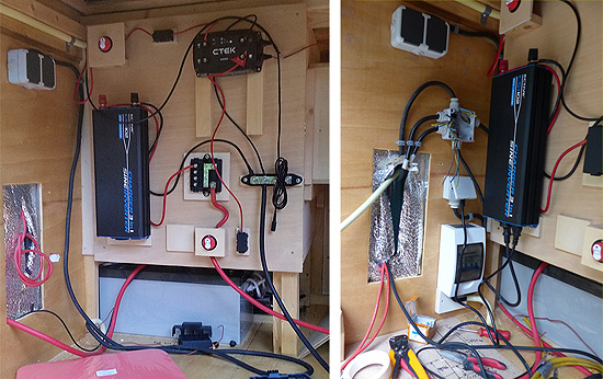
Using the electrical schematics we connected all the cables and wires. Step by step we tested the system and everything worked fine.

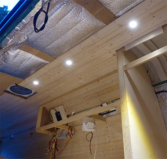
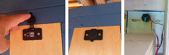
In the living area we installed three USB chargers. One above the double bed, one at our table and one above the workspace above the fridge.
We connected all the LED strips and LED spots in the ceiling. Switches of our lights are placed "decentralized", namely in the location were the lights most likely are switched. All appliances (fan, fridge, water pump, etc) are also connected to the fusebox.
Only the ambient LED strips around our double bed we upgraded with a simple remote digital dimmer, which works great. We might just use these on other lights in the van.
Besides the 12V system, which powers all of our appliances, we have the three 230V outlets, which are just for recharging our batteries of our laptop & camera's.
As you can see the electrical panel in the garage is very easily accessible. Especially when we start using the campervan we want to have quick access to the panel just in case. We plan to cover the panel later on with a seperator cover, so we can put more stuff in the back, without the risk of damaging the components or wires.
Also check out ourvideo about installing our electrical system.